
- ACTIVITY DIAGRAMS DEFNATION VERIFICATION
- ACTIVITY DIAGRAMS DEFNATION SOFTWARE
- ACTIVITY DIAGRAMS DEFNATION LICENSE

Consequent to these enhancements, SysML is able to model a wide range of systems, which may include hardware, software, information, processes, personnel, and facilities. The former can be used for requirements engineering the latter can be used for performance analysis and quantitative analysis. SysML's diagrams express system engineering concepts better due to the removal of UML's software-centric restrictions and adds two new diagram types, requirement and parametric diagrams.These improvements include the following:
ACTIVITY DIAGRAMS DEFNATION SOFTWARE
SysML offers several systems engineering specific improvements over UML, which has been developed as a software modeling language. The language's extensions were designed to support systems engineering activities. SysML is defined as an extension of a subset of the Unified Modeling Language (UML) using UML's profile mechanism.
ACTIVITY DIAGRAMS DEFNATION LICENSE
SysML was originally developed by an open source specification project, and includes an open source license for distribution and use.
ACTIVITY DIAGRAMS DEFNATION VERIFICATION
It supports the specification, analysis, design, verification and validation of a broad range of systems and systems-of-systems. In the edit field below the list box, enter the constraint expression for this action.The systems modeling language ( SysML) is a general-purpose modeling language for systems engineering applications. The possible options are OCL and plain text.

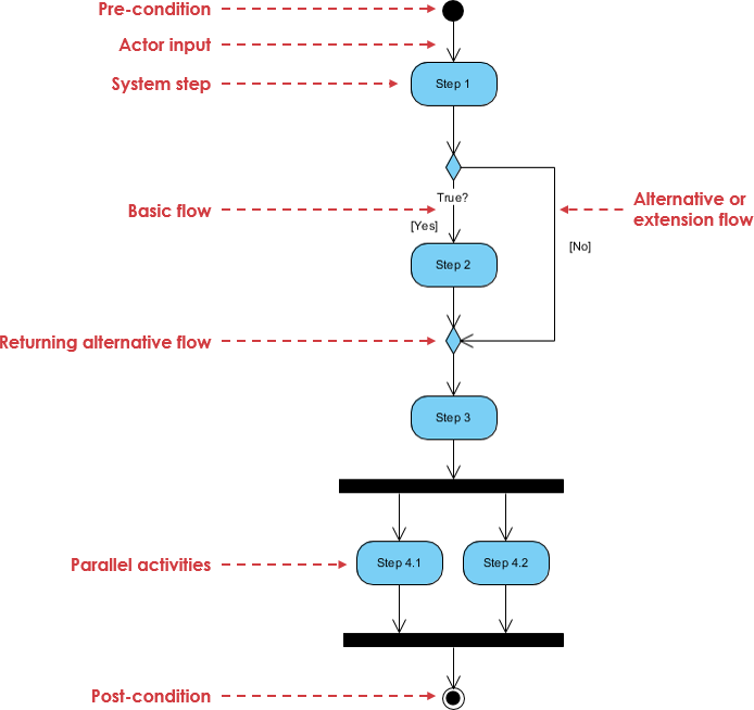
By flow, we mean that the execution of one node affects and is affected by the execution of other nodes, and such dependencies are represented by edges in the activity diagram. The semantics of activities is based on token flow. The execution of an action represents some transformation or processing in the modeled system, be it a computer system or otherwise. An action is an executable activity node that is the fundamental unit of executable functionality in an activity, as opposed to control and data flow among actions. An activity represents a behavior which is composed of individual elements that are actions. An action represents a single step within an activity, that is, one that is not further decomposed within the activity. Actions are not states (compared to UML 1.x) and can have subactions. In UML 2.0, activities consist of actions. If an action can be broken into a sequence of other actions, you can create an activity to represent them. Actions are the basic units of the system behavior.Īn Activity diagram enables you to group and ungroup actions. The activity diagram enables you to model the system behavior, including the sequence and conditions of execution of the actions.

Go Up to UML 2.0 Activity Diagrams Definition


 0 kommentar(er)
